
Advanced Operations
This page covers specialized operations for complex harness design tasks.
Copy Wire
Creates a new wire by copying properties from an existing wire and connecting it between specified pins.
When to use:
- Creating parallel connections with same properties
- Mirroring wire patterns
- Replicating signal routing
How to use:
Via Context Menu:
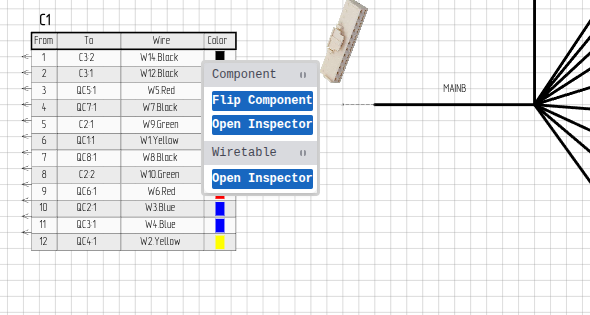
 click on a wire row in a wire table
- Select Copy Wire
 click on the start pin, then the end pin
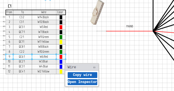 Context menu: Wire row with Copy Wire option
Via Script:
Script.copyWire({
  prototypeWireQuery: "WIRE_NAME", // Wire to copy properties from
  startPinQuery: { componentName: "ECU1", pinName: "1" },
  endPinQuery: { componentName: "ECU2", pinName: "1" },
});
What Gets Copied
- Wire color
- Wire gauge
- Part number
- Other wire properties
A new wire is created with properties copied from the prototype wire, connected between the specified start and end pins.
Merge Anchors
Combines two anchor points into a single anchor - useful for cleaning up routing or creating junction points.
When to use:
- Simplifying complex bundle routing
- Creating clean junction points
- Fixing overlapping anchors
How to use:
Via Context Menu:
- click on an anchor
- Select Merge with Another Anchor
- click on the second anchor to merge with
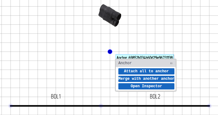 Context menu: Merge with Another Anchor option
Via Script:
Script.mergeAnchors({
  main: { id: "anchor-id-1" },
  secondary: { id: "anchor-id-2" },
});
The main anchor is kept and the secondary anchor is merged into it.
Behavior:
- All wires routing through the secondary anchor now route through the main anchor
- Bundle segments reconnect to the main anchor
- The secondary anchor is deleted
Make Sideview
Creates a sideview for a component — a visual representation of the connector shell (the physical connector body as seen from the side). Supports three modes.
When to use:
- Showing the physical connector appearance
- Adding connector shell images from datasheets
- Visual documentation for assembly
- Batch-creating sideviews for components with image data from DigiKey
Mode 1: From Existing Image on Canvas
Import or draw an image, then attach it to a component.
Via Context Menu:
- Import an image (SVG, PNG, JPG, etc.) of the connector shell
- click on the image to open the context menu
- Select Create Sideview
- click on the component's wire table or pinout to link thesideview
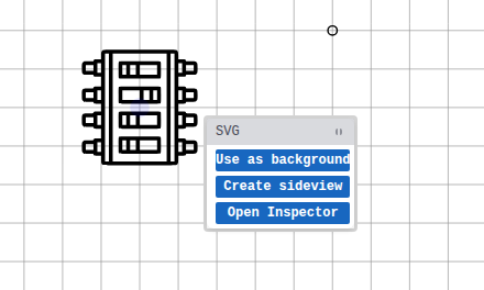 Context menu: Create Sideview option
Via Script:
Script.makeSideview({
  image: { type: "image", query: { id: "image-id" } },
  component: { query: "J101" },
});
The image parameter specifies the image element to use, and component specifies which component to link it to. The image is merged into the component's anchor and converted to a sideview.
Mode 2: From Component's Own Image Data
Uses the component's imageData and imageType properties — typically populated from DigiKey. No pre-drawn image needed.
Script.makeSideview({
  component: { query: "J101" },
  useComponentImageData: true,
  autoScale: true,
});
Batch Creation
This mode is ideal for batch scripts that create sideviews for all components that have image data. See the batch example below.
Mode 3: From Explicit Image Data
Pass base64 image data directly.
Script.makeSideview({
  component: { query: "J101" },
  pathData: "data:image/png;base64,iVBORw0KGgo...",
  pathDataType: "png",
  scale: { x: 2.0, y: 2.0 },
  coords: { x: -200, y: 0 },
});
Common Options (Modes 2 & 3)
| Option | Type | Default | Description |
|---|---|---|---|
autoScale | boolean | false | Auto-calculate scale to fit ~150 px sideview size |
scale | object | {x:1, y:1} | Explicit scale factors; overrides autoScale |
coords | object | {x:-200, y:0} | Offset from the component's anchor |
transparentColor | string | — | Color to make transparent, e.g. "#ffffff" |
transparentColorTolerance | number | — | Tolerance for transparent color matching |
createRevision | boolean | true | Set false in batch scripts (the script runner already creates one) |
Batch Example
Create sideviews for every component that has image data but no sideview yet:
const allComponents = Script.queryComponent({});
let created = 0,
  skipped = 0,
  noImage = 0;

for (const comp of allComponents.elements) {
  if (!comp.imageData || !comp.imageType) {
    noImage++;
    continue;
  }
  const sv = Script.querySideview({
    query: { componentId: comp._id.toString() },
  });
  if (sv.elements && sv.elements.length > 0) {
    skipped++;
    continue;
  }
  Script.makeSideview({
    component: { query: { name: comp.name } },
    useComponentImageData: true,
    autoScale: true,
    createRevision: false,
  });
  created++;
}

scriptConsole.log(
  "Done! Created: " +
    created +
    ", Already had sideview: " +
    skipped +
    ", No image data: " +
    noImage
);
Sideview Properties
In the Inspector, you can configure:
| Property | Description |
|---|---|
| Image | Connector shell image (SVG or raster) |
| Pin labels | Show/hide pin numbers |
| Orientation | Rotate the view |
| Scale | Adjust size |
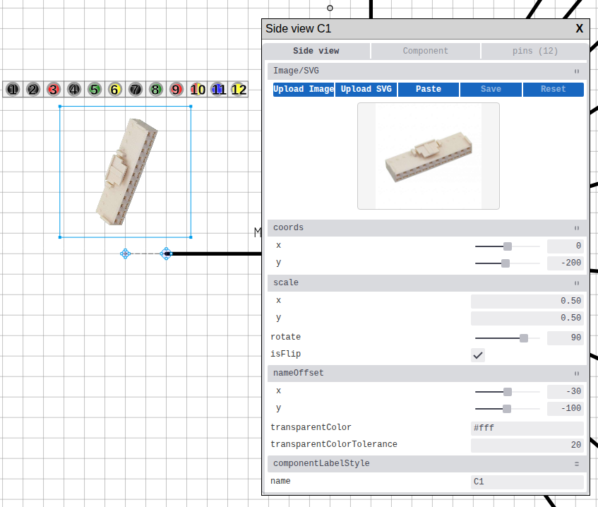 Sideview configuration in Inspector
Convert to Sideview
Converts an image into a sideview linked to a component.
When to use:
- Converting imported connector shell images into functional sideviews
- Linking graphics to components
How to use:
Via Context Menu:
- click on the image to open the context menu
- Select Convert to Sideview
- click on the component's wire table or pinout to link thesideview
Via Script:
Script.convertToSideview({
  type: "image",
  query: { id: "image-element-id" },
});
The command converts the image into a sideview. You then select which component to link it to.
Bundle Splice Creation
Creates a named splice point at a bundle junction — important for manufacturing documentation.
When to use:
- Marking wire splice locations
- Creating branch points in harness
- Documenting where wires split off
How to use:
Via Tool (Recommended):
- Select the Bundle Splice tool from the Toolbar
- click on a bundle anchor point
- Fill in the splice properties dialog (name, part number, appearance)
- Submit to place the splice
Via Context Menu (converting existing image):
- Import an image to use as the splice marker
- Merge the image's anchor with an anchor that is shared by two bundles (see Merge Anchors)
- click on the image
- Select Convert to Bundle Splice — this option only appears when the image's anchor is shared by two bundles
- The image becomes a splice marker at that junction
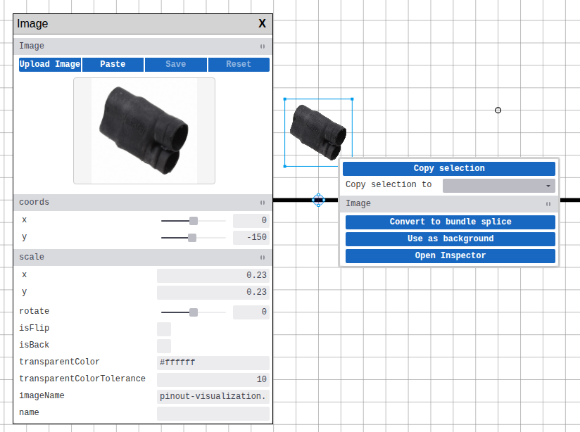 Context menu: Convert to Bundle Splice option
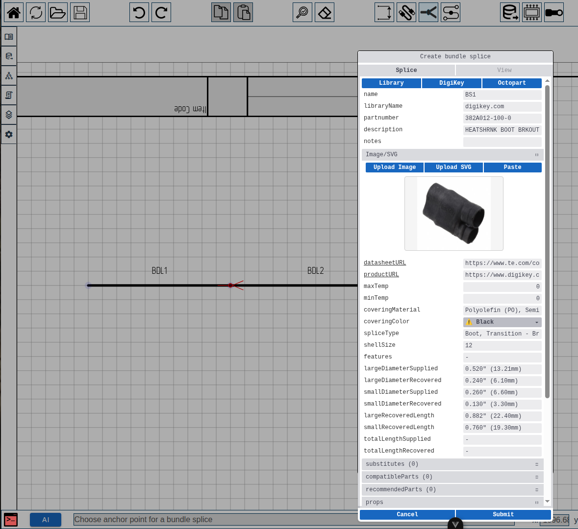 Bundle splice creation dialog
Script API
Bundle splice creation via script command is not currently implemented. Use the toolbar tool or context menu conversion.
Splice Properties:
| Property | Description |
|---|---|
| Name | Identifier on drawing |
| Part Number | Manufacturing PN |
| Covering Material | Material type |
| Covering Color | Color code |
Attach All to Anchor
Converts all independent root anchors on the sheet into children of a single parent anchor. Child anchors become positioned relative to the parent and move together with it.
When to use:
This is essential when creating library components. A library sheet often contains a component plus related elements (dimensions, images, text labels). By attaching all anchors to the component's main anchor, everything moves as a unit when a user places the library item on their drawing.
How to use:
- Create your component and any related elements (dimensions, images, etc.)
- click on the component's root anchor
- Select Attach all to anchor
All other root anchors on the sheet are re-parented to the selected anchor.
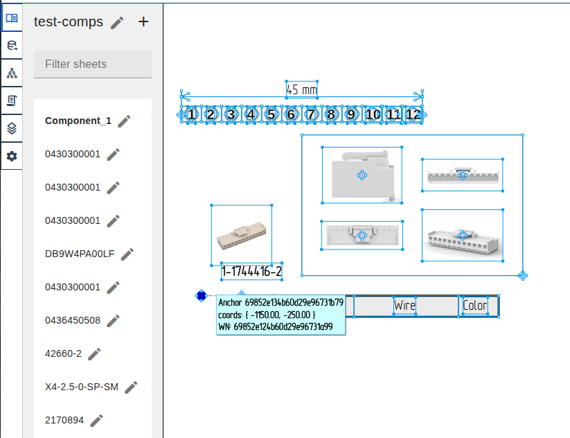 Library template: all elements attached to a single anchor for unified placement
Rehang Wire
Moves a wire connection from one pin to another - useful for fixing routing errors or reassigning connections.
When to use:
- Correcting wiring mistakes
- Reassigning connections during redesign
- Moving wires between pins on same or different components
How to use:
Via Drag:
- Select the wire endpoint
- Drag to the new pin
- Release to connect
Via Script:
You can rehang the start pin, end pin, or both:
// Rehang start pin only:
Script.rehangWire({
  wire: "PWR_MAIN",
  newStart: { componentName: "ECU2", pinName: "1" },
});

// Rehang end pin only:
Script.rehangWire({
  wire: "PWR_MAIN",
  newEnd: { componentName: "ECU3", pinName: "2" },
});

// Rehang both ends:
Script.rehangWire({
  wire: "PWR_MAIN",
  newStart: { componentName: "ECU2", pinName: "1" },
  newEnd: { componentName: "ECU3", pinName: "2" },
});
Important notes:
- The wire maintains its properties (color, gauge, etc.)
- Length recalculates based on new routing
newStartandnewEndcan be used independently or together
Bundle Break Operations
Bundle breaks are visual markers indicating that the drawn bundle length does not reflect its actual physical length.
Add Bundle Break:
Inserts a visual break in a bundle segment:
Via Tool:
- Select the Bundle Break tool from the toolbar
- click on the bundle where you want the break
Via Script:
Script.drawBundleBreak({
  bundleName: "MAIN_TRUNK",
  offset: 0.5, // Position along bundle (0.0 = start, 1.0 = end)
});
Remove Bundle Break:
Via Context Menu:
- click on a bundle part
- Select Remove Break
Via Script:
Script.removeBundleBreak({
  bundleName: "MAIN_TRUNK",
});
When to use bundle breaks:
- When the drawn bundle is visually shortened but represents a longer real-world path
- When bundle length in the drawing doesn't match the physical harness length
- When a bundle visually terminates at the sheet edge but continues in reality
Bundle Bend Operations
Add or remove bend points (corners) in bundles for routing control.
Add Bundle Bend:
Splits a bundle segment into two at the bend point:
Via Context Menu:
- click on a bundle segment
- Select Add Bend
- The bend is placed at the click location
Via Script:
Script.addBundleBend({
  bundleName: "MAIN_TRUNK",
  point: { x: 250, y: 200 },
});
Remove Bundle Bend:
Merges two adjacent segments back into one:
Via Context Menu:
- click on a bend anchor (the point where two segments meet)
- Select Remove Bend
Via Script:
Script.removeBundleBend({
  anchorID: "bend-anchor-id",
});
WARNING
Removing a bend also removes any bundle breaks on the affected segments.
Sheet Wire Table
A sheet wire table shows all wires on the current sheet in a single table.
How to create:
Via Command Palette:
- Open the Command Palette
- Run Create sheet wire table
Each sheet can have at most one sheet wire table. Component-level wire tables are created automatically as part of component creation.
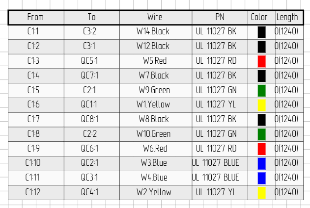 Sheet wire table
Practical Examples
Example 1: Merging Nearby Anchors
// Get all anchors in the project
const result = Script.queryAnchor({});
const anchors = result.elements;

// Find pairs of anchors that are close together
for (let i = 0; i < anchors.length; i++) {
  for (let j = i + 1; j < anchors.length; j++) {
    const a = anchors[i];
    const b = anchors[j];
    if (Math.abs(a.x - b.x) < 10 && Math.abs(a.y - b.y) < 10) {
      // Merge the second anchor into the first
      Script.mergeAnchors({
        main: { id: a.id },
        secondary: { id: b.id },
      });
      scriptConsole.log(`Merged anchor ${b.id} into ${a.id}`);
    }
  }
}
Finding bundle anchors
queryAnchor doesn't support filtering by bundle. Query all anchors and filter in JavaScript based on position or other properties.
Example 2: Batch-Create Sideviews from DigiKey Image Data
Create sideviews for all components that have image data (e.g. from DigiKey) but no sideview yet. See Make Sideview — Batch Example for the full version.
const allComponents = Script.queryComponent({});
for (const comp of allComponents.elements) {
  if (!comp.imageData || !comp.imageType) continue;

  const sv = Script.querySideview({
    query: { componentId: comp._id.toString() },
  });
  if (sv.elements && sv.elements.length > 0) continue;

  Script.makeSideview({
    component: { query: { name: comp.name } },
    useComponentImageData: true,
    autoScale: true,
    createRevision: false,
  });
}
Example 3: Adding Breaks to Long Bundles
// Get all bundles and add breaks to those longer than 500mm
const result = Script.queryBundle({});
const bundles = result.elements;

for (const bundle of bundles) {
  if (bundle.length > 500) {
    // Add a break in the middle of long bundles
    Script.drawBundleBreak({
      bundleName: bundle.name,
      offset: 0.5,
    });
    scriptConsole.log(`Added break to ${bundle.name}`);
  }
}
Context Menu Quick Reference
available options depend on what you've selected.
By Element Type
Components are represented by wire tables, sideviews, and pinouts.
element-specific options.
| Element | Available Actions |
|---|---|
| Bundle Part | Add Bend, Add Break / Remove Break, Open Inspector |
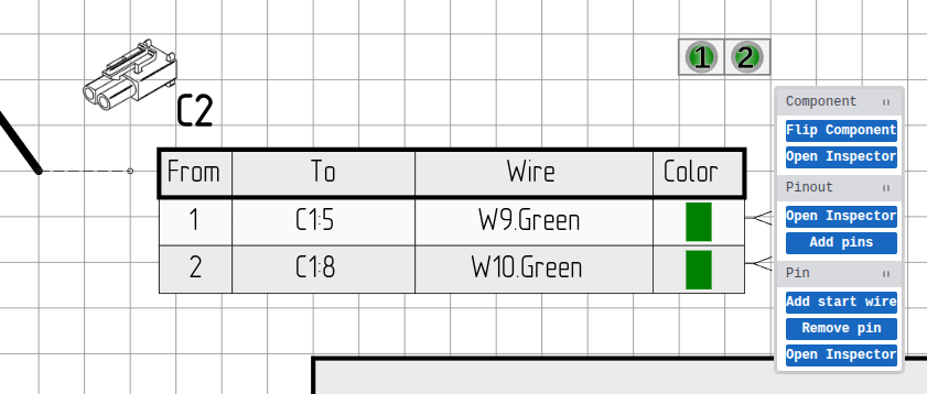
| Pinout | Flip Component, Add Pins, Open Inspector |
| Sideview | Flip Component, Open Inspector |
| Wire Table (caption) | Flip Component, Open Inspector |
| Wire Table (row) | Copy Wire, Open Inspector |
| Pin (in pinout) | Add Start/End Wire, Remove Wire, Remove Pin, Open Inspector |
| Anchor | Attach All to Anchor, Merge with Another Anchor, Remove Bend (bend anchors), Open Inspector |
| Image | Convert to Sideview, Convert to Bundle Splice, Use as Background, Create Sideview, Open Inspector |
| Selection | Copy Selection, Copy Selection to (sheet), Paste |
| Script (sidebar) | Delete |
Note: Some options are contextual:
- After selecting "Convert to Sideview" or "Create Sideview", click on a component's wire table or pinout to link the sideview
- "Convert to Bundle Splice" appears only when the image's anchor is merged with an anchor shared by two bundles
- Anchor options appear only for root anchors
Context menu: Wire row in wire table
 Context menu: Wire table caption
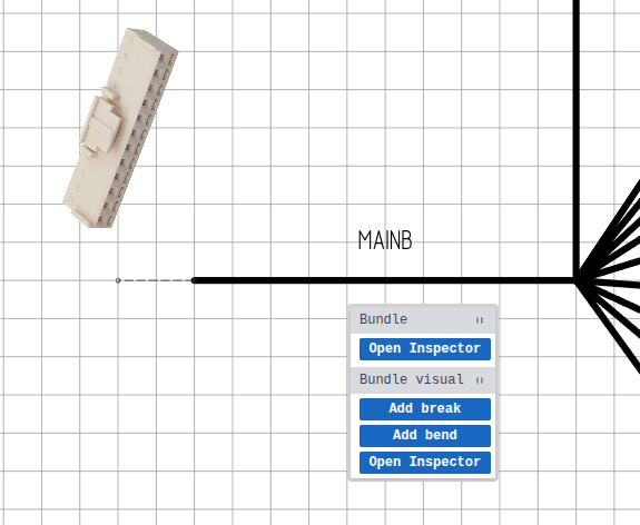 Context menu: Bundle
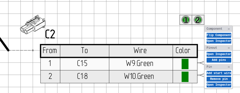 Context menu: Pinout
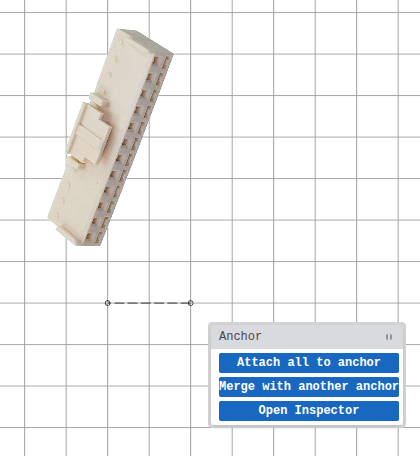 Context menu: Anchor
 Context menu: Pin in pinout
Context menu: Image
Operations Quick Reference
| Operation | Target Element | Script Command |
|---|---|---|
| Copy Wire | Wire row | copyWire |
| Merge Anchors | Anchor | mergeAnchors |
| Make Sideview | Image | makeSideview |
| Convert to Sideview | Image | convertToSideview |
| Convert to Splice | Image | - |
| Add Bundle Bend | Bundle Part | addBundleBend |
| Remove Bundle Bend | Bend Anchor | removeBundleBend |
| Add Bundle Break | Bundle (via tool) | drawBundleBreak |
| Remove Bundle Break | Bundle Part | removeBundleBreak |
| Rehang Wire | Wire endpoint | rehangWire |
| Flip Component | Component | - |
| Attach All to Anchor | Anchor | - |
Next Steps
- Components Reference - Component properties and features
- Bundles Reference - Bundle routing and management
- Command Reference - Full script API