
Core Concepts
This page explains the fundamental terminology and concepts in LoomCAD. Understanding these will help you navigate the rest of the documentation.
Project Structure
Project
A project is the top-level container for your wire harness design. It holds all sheets, components, wires, and settings for a single harness or product.
- Projects are saved automatically to the cloud
- Each project has a unique name
- Projects can be exported as JSON for backup
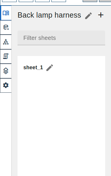
Sheet
A sheet is a single drawing page within a project. Complex harnesses may use multiple sheets.
- Each sheet has its own canvas
- Sheets appear as tabs in the side menu
- Wires can span across sheets (cross-references)
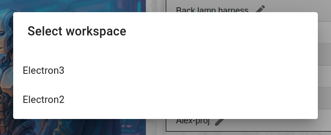
Workspace
A workspace groups multiple projects together. Use workspaces to organize by customer, product line, or team.
Design Elements
Component
A component represents a physical part in your harness: connectors, terminals, ECUs, sensors, relays, etc.
| Property | Description |
|---|---|
| Name | Display label (e.g., "ECU1", "J101") |
| Part Number | Manufacturer part number |
| Manufacturer | Component manufacturer |
| Pins | Connection points on the component |
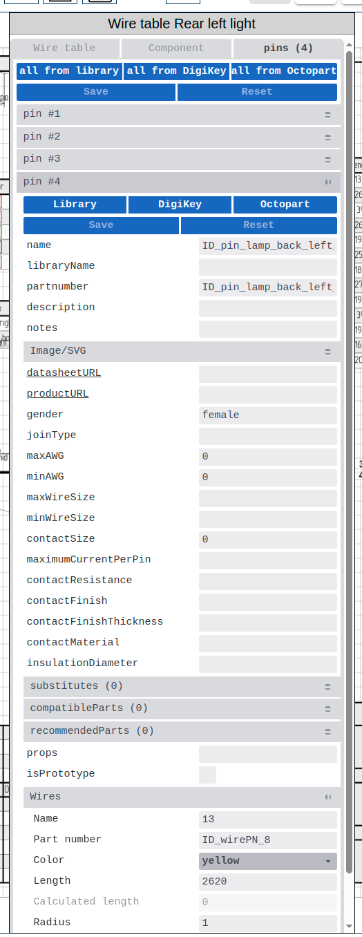
Pin
A pin is a connection point on a component. Wires connect to pins.
Pin properties:
- Pin number/name
- Pin function (power, ground, signal)
- Wire assignment
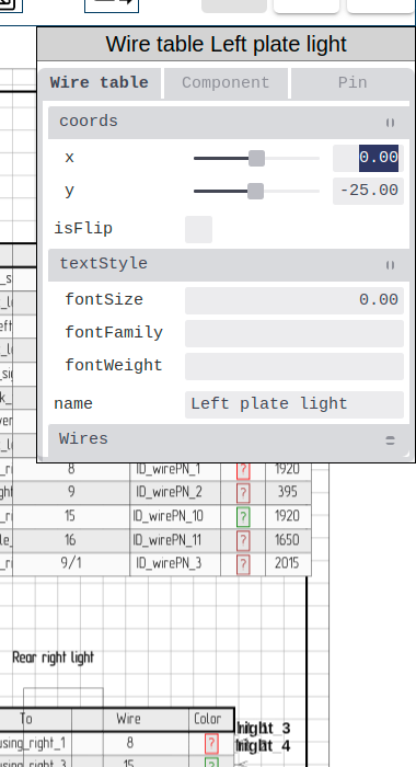
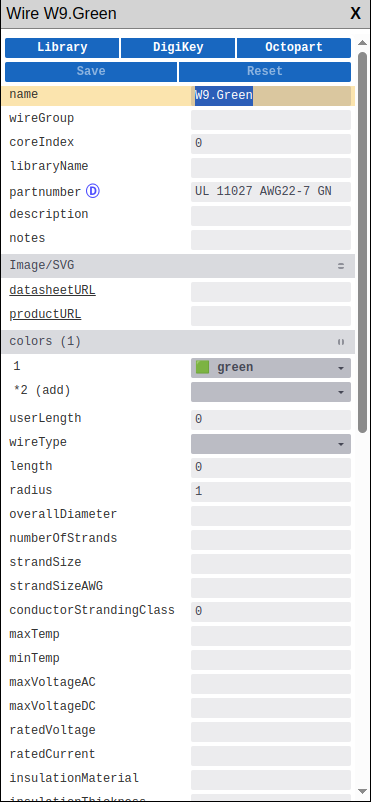
Wire
A wire is an electrical connection between two pins. In LoomCAD, wires are logical connections - the physical routing is handled by bundles.
| Property | Description |
|---|---|
| Color | Wire insulation color (DIN 47100 codes) |
| Gauge | Wire size (AWG or mm²) |
| From/To | Source and destination pins |
| Length | Calculated from bundle routing |
Bundle
A bundle represents the physical wire harness path. Multiple wires travel together through bundle segments.
Think of bundles as the "tubes" that wires route through:
- Draw bundles to define harness geometry
- Wires automatically route through bundles
- Bundles determine wire lengths
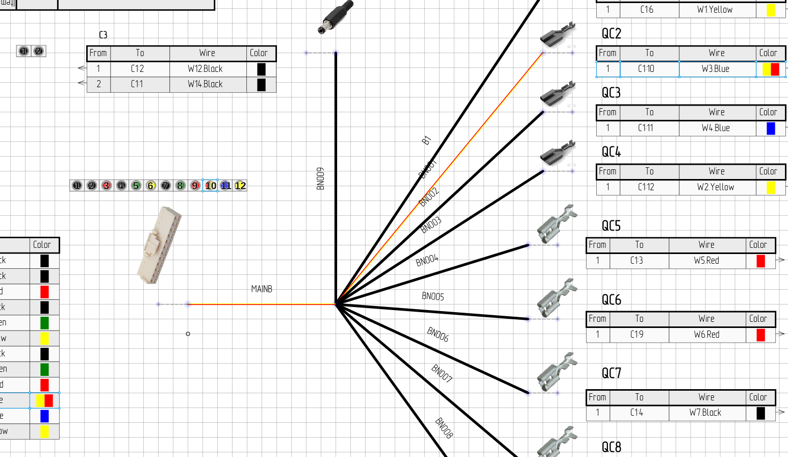 Click a wire in the wire table to highlight its bundle path (bundles change to wire color)
Bundle Splice
A bundle splice is a manufactured element placed at a junction where bundles meet. It represents the physical splice point and carries manufacturing properties like part number, covering material, and temperature ratings.
Splices are created using the Bundle Splice tool from the toolbar, or by converting an image at a bundle junction via context menu.
Visual Elements
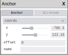
Anchor
An anchor is a reference point that other elements link to. Think of anchors as "attachment points" that hold your design together.
How anchors work:
- Components, bundles, and other elements link to anchors
- Moving an anchor moves ALL elements linked to it
- Bundles connect between two anchors (start and end)
- Use anchors to group and reposition related elements together
Example: If a connector and several wires are linked to the same anchor, moving that anchor repositions everything at once.
Pinout
A pinout is a visual diagram showing a component's pin arrangement. LoomCAD can display:
- Inline pinouts (on the component symbol)
- Side views (showing connector shell)
 Pinout showing pin connections
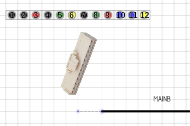
Sideview
A sideview is a visual representation of the connector shell - the physical connector body as seen from the side.
- Shows the actual connector appearance
- Can use manufacturer images (SVG or raster) from datasheets
- Linked to component data
Dimension
A dimension is a measurement annotation showing distances on your drawing.
- Add dimensions for manufacturing clarity
- Dimensions can be manual or automatic
Data Management
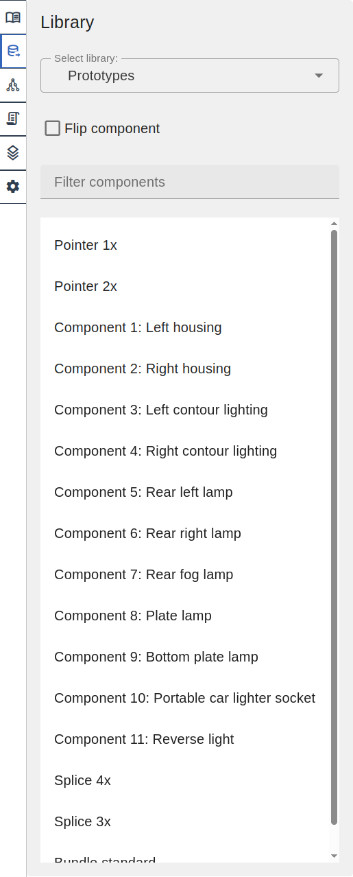
Library
A library is a collection of reusable drawing templates. Unlike traditional CAD libraries that store only component metadata, LoomCAD libraries contain complete drawing sheets — a library item can include multiple components, bundles, wires, dimensions, and annotations as a single reusable template.
| Library Type | Description |
|---|---|
| Built-in Library | Common connectors included with LoomCAD |
| DigiKey Integration | Search and import from DigiKey catalog |
| User Library | Your saved custom templates |
| Library Project | A project designated for sharing reusable drawings |
Script
A script is JavaScript code that automates design tasks. Scripts can:
- Create components programmatically
- Modify wire properties in bulk
- Generate repetitive elements
- Validate designs
Scripts can be saved to library projects for reuse across designs.
Manufacturing Output
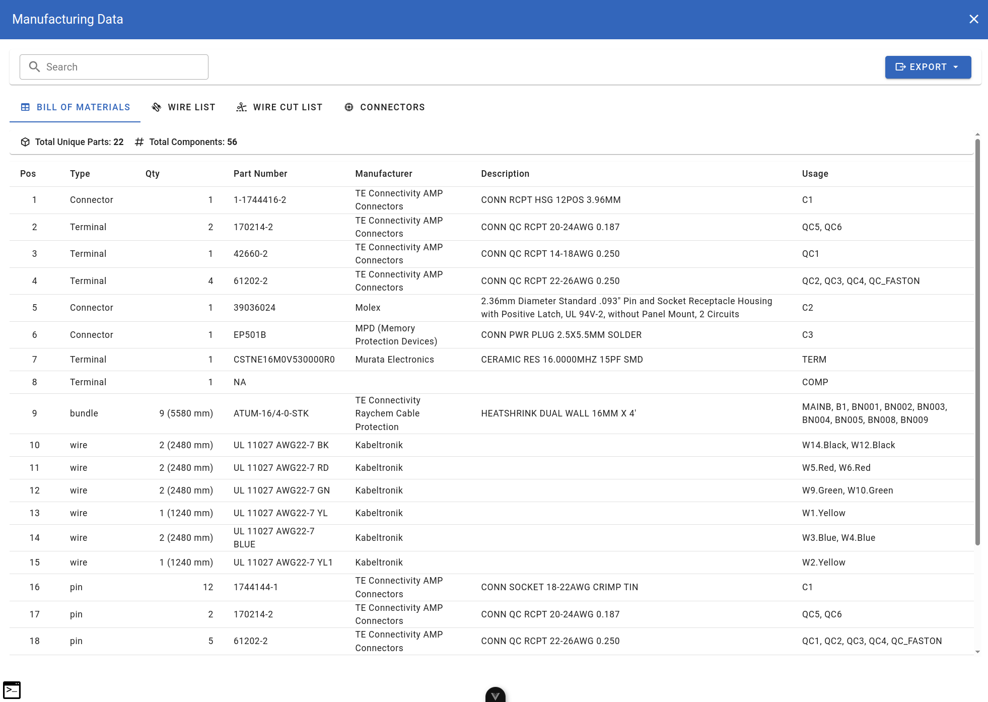
BOM (Bill of Materials)
The BOM lists all components in your design with quantities, part numbers, and descriptions.
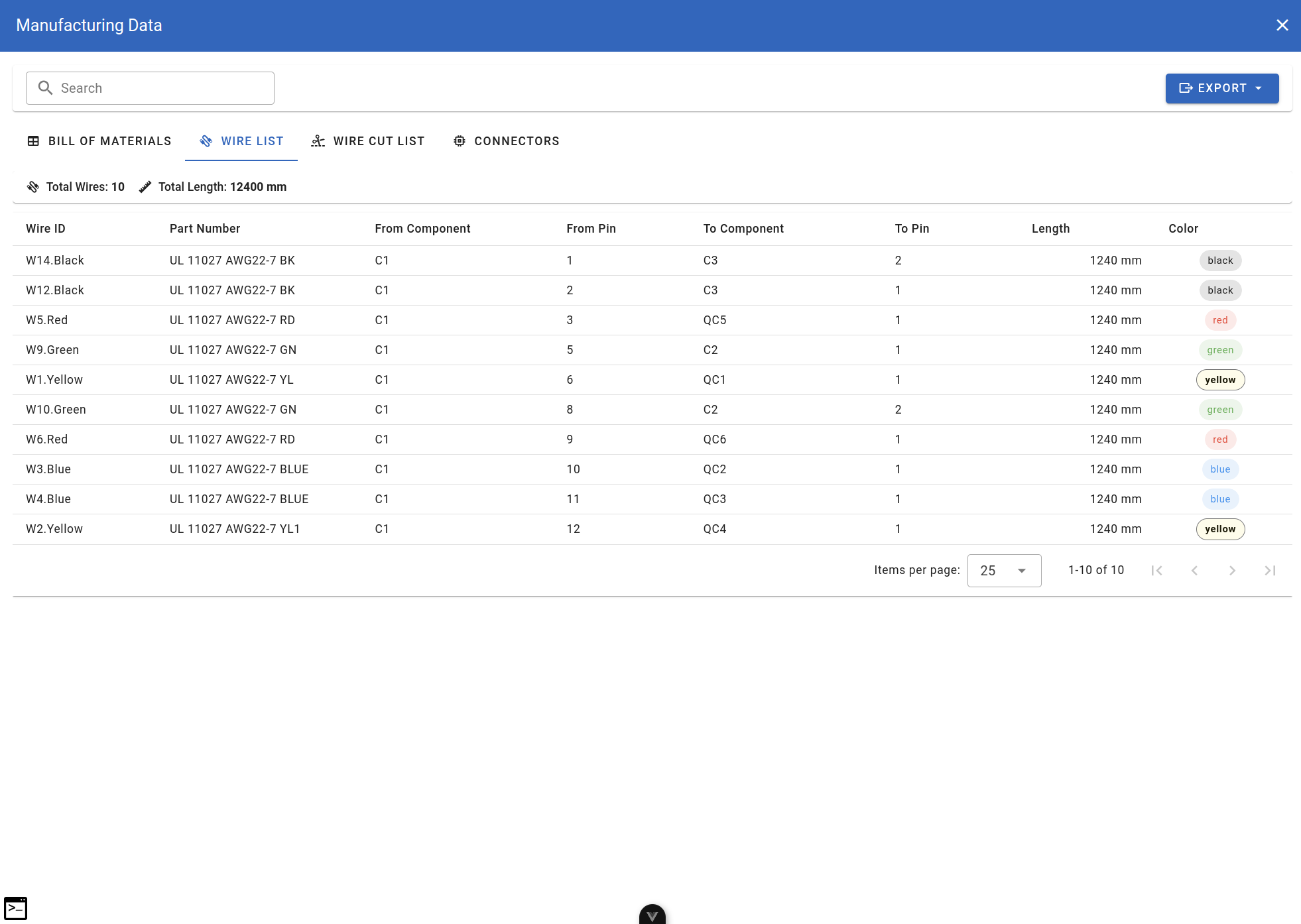
Wire List
The wire list enumerates all wires with their properties: from/to, color, gauge, length.
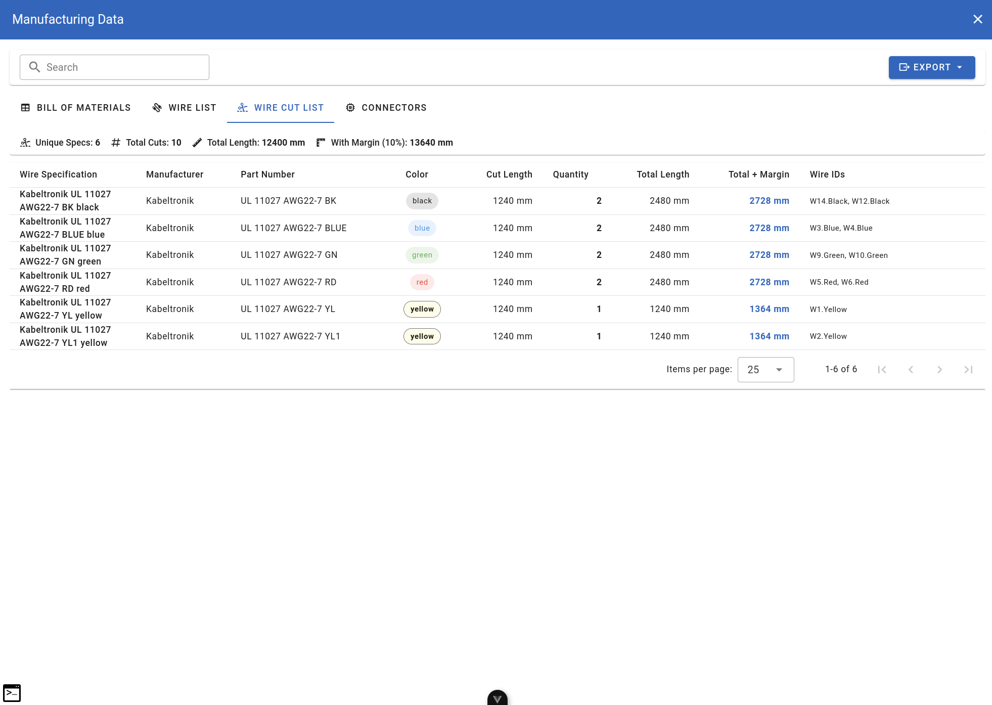
Wire Cut List
The wire cut list is a manufacturing-ready document showing wire lengths for cutting and preparation.
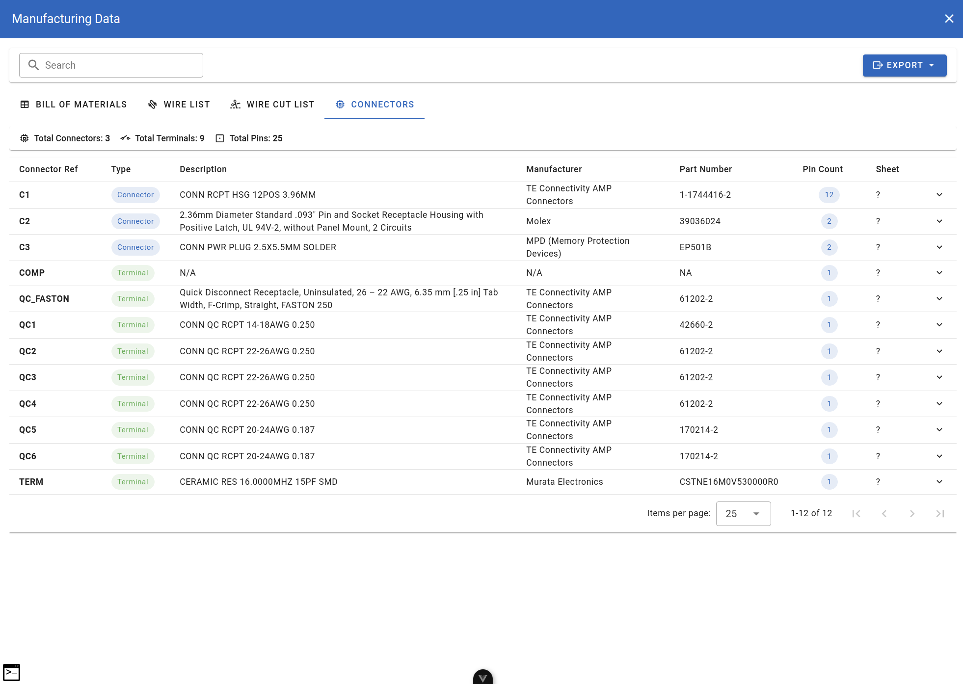
Connector Summary
The connector summary shows each connector with its pin assignments and connected wires.
AI & Automation
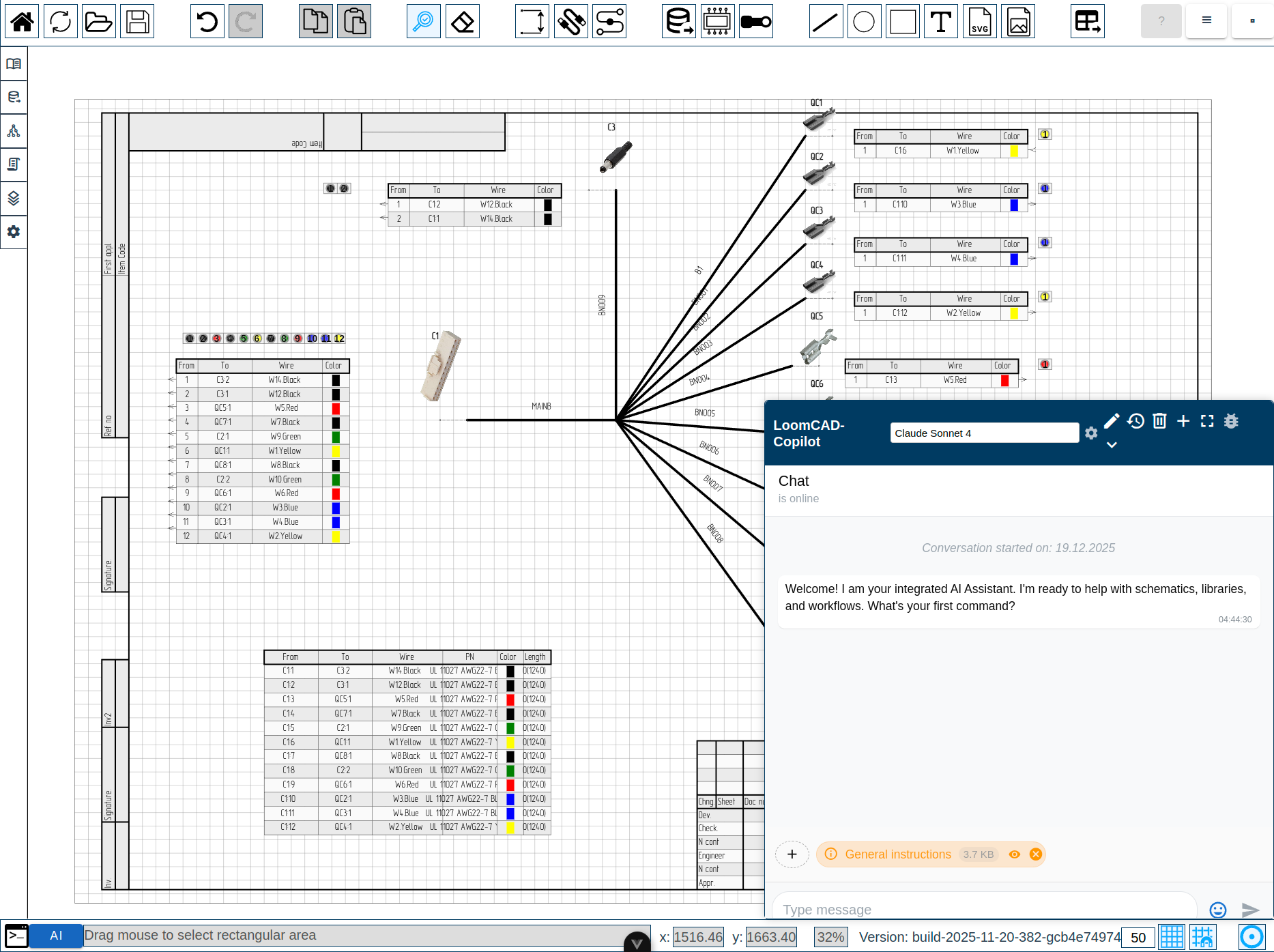
AI Copilot
The AI copilot is an integrated assistant that helps with design tasks. It can:
- Answer questions about your design
- Generate scripts from natural language
- Validate harness connections
- Suggest solutions to problems
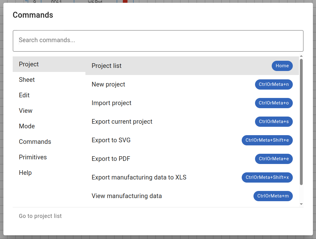
Command Palette
The command palette provides quick access to all LoomCAD actions. Press Space to open.
Script Commands
Script commands are the API functions available in scripts. Categories include:
| Category | Examples |
|---|---|
| Draw | drawComponent, drawWire, drawBundle |
| Query | queryComponent, queryWire, queryPin |
| Update | updateComponent, updateWire |
| Move | move |
| Erase | eraseComponent, eraseWire |
Quick Reference: Element Hierarchy
- Anchors (link elements)
- Visual Elements (lines, dimensions, shapes, text, images)
- Sheet 2...
Color Standards
LoomCAD supports DIN 47100 color codes for wire identification:
| Code | Color | German |
|---|---|---|
| WH | White | Weiss |
| BN | Brown | Braun |
| GN | Green | Grün |
| YE | Yellow | Gelb |
| GY | Grey | Grau |
| PK | Pink | Rosa |
| BU | Blue | Blau |
| RD | Red | Rot |
| BK | Black | Schwarz |
| VT | Violet | Violett |
| OG | Orange | Orange |
Combine codes for striped wires: RD/WH = Red with White stripe.
Next Steps
Now that you understand the concepts:
- Getting Started - Learn the interface
- Your First Harness - Hands-on tutorial
- AI Copilot Overview - Work with AI assistance